F-103 Excalibur Model

Adm_maverick

Rear Admiral
Wing Commander 3: Heart of the Tiger is one of my favorite games of all times, and I absolutely loved piloting the Excalibur fighter in the game. So this is my effort to scratch-build a large scale (about 16" long) model of it. This is going to be a long term project. So this is going to be my project thread on here as I work through the project.

I did a paper-craft version of the F-109 Vampire recently, and that really rekindled an old interest I've had to have a model of the F-103 Excalibur.

I'll warn everyone now, this is going to take a while to complete. It will also be my first totally scratch built and self-designed model. The real challenge... I have no actual 3D design experience or systems. So I'm doing this all as I figure it out. Who wants to go on an adventure?

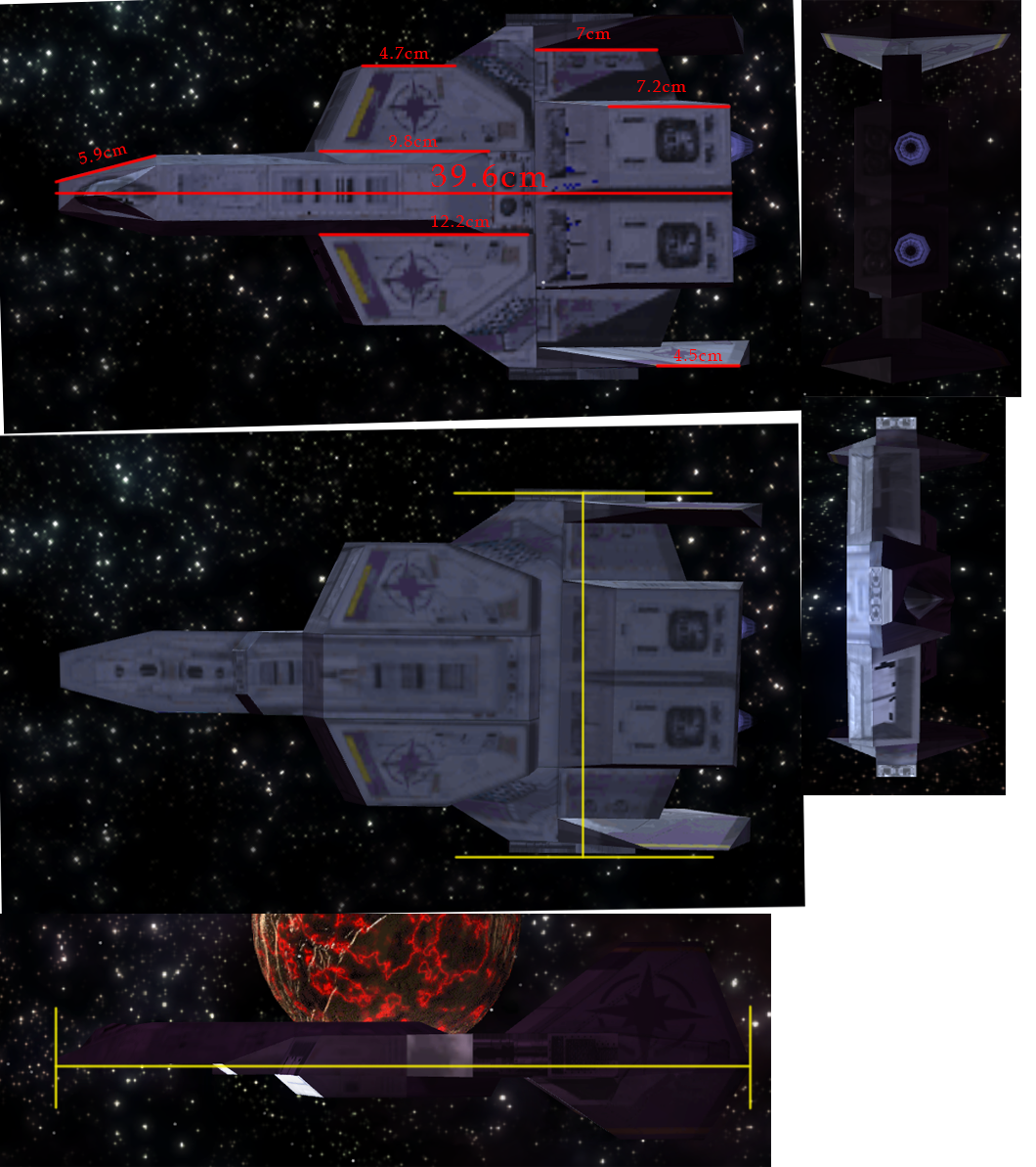
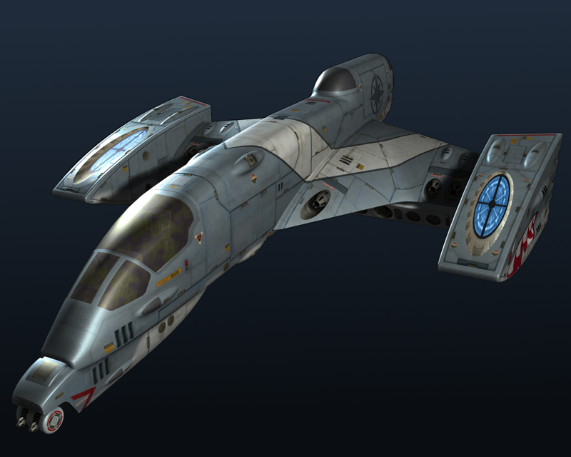
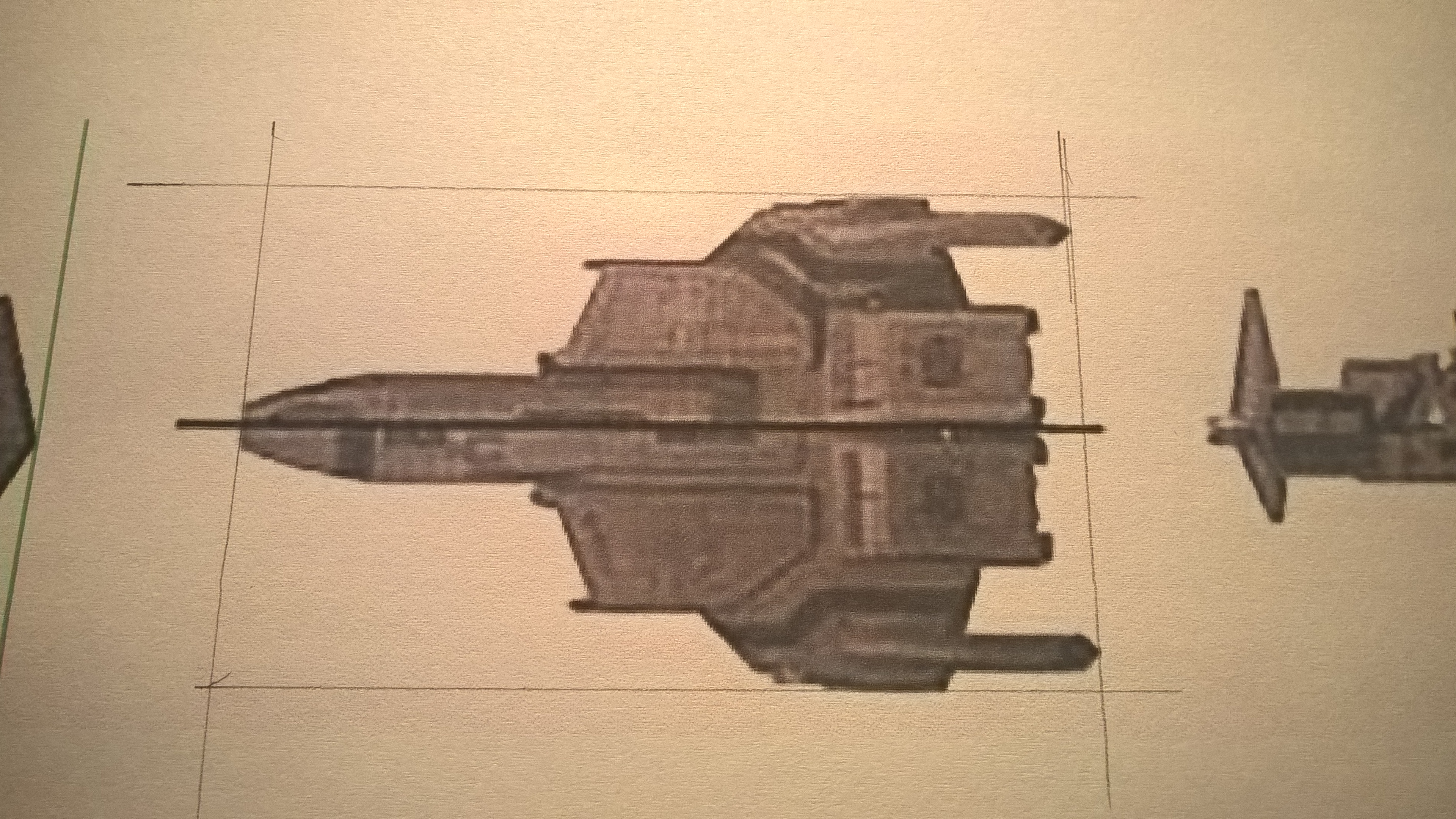
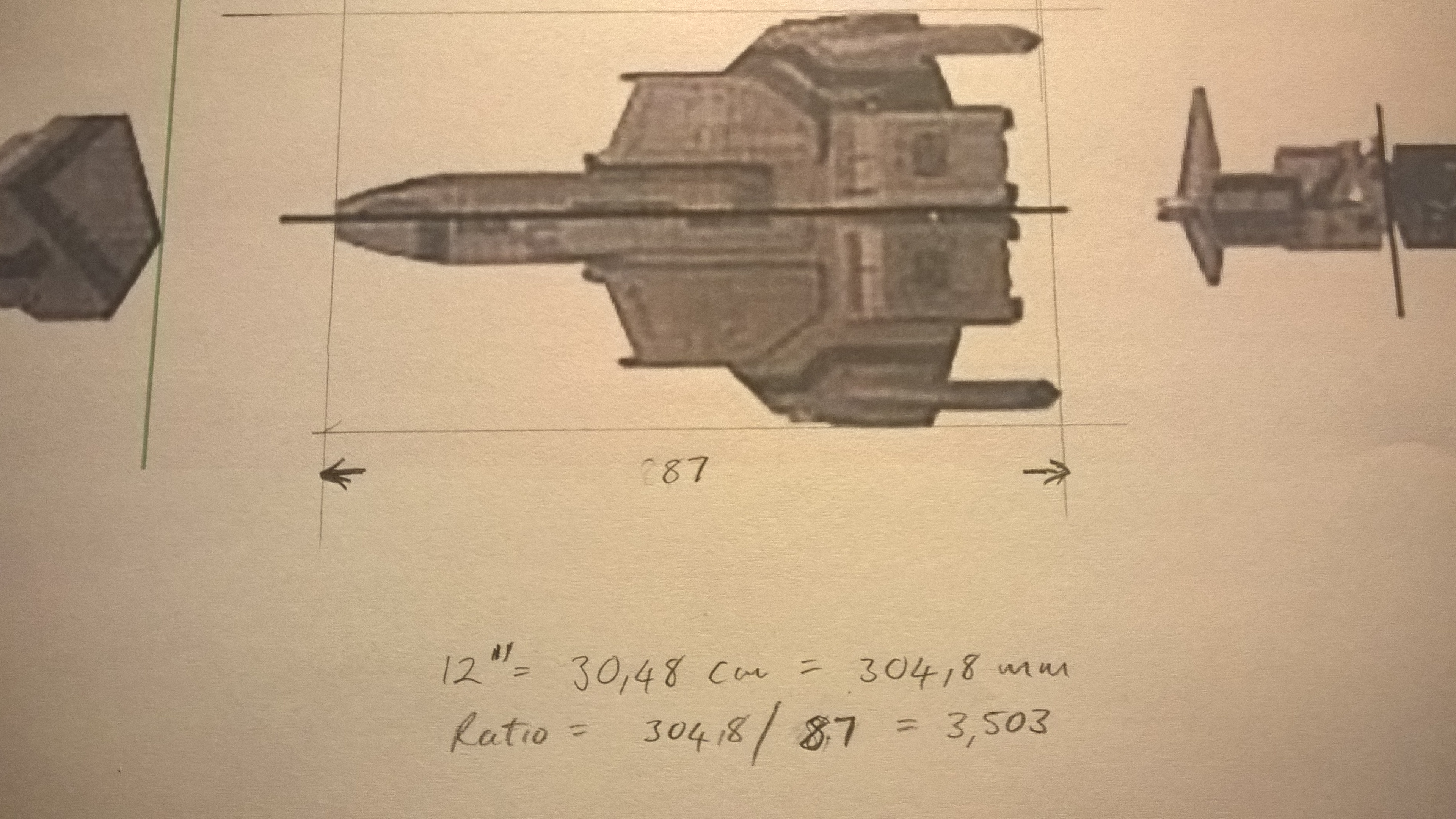
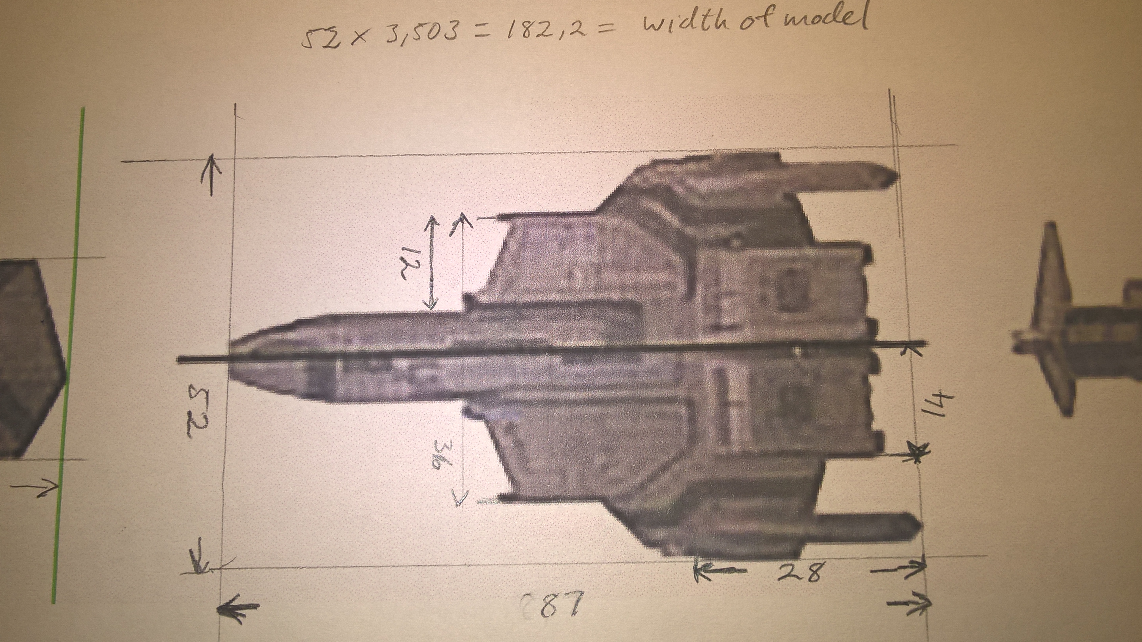
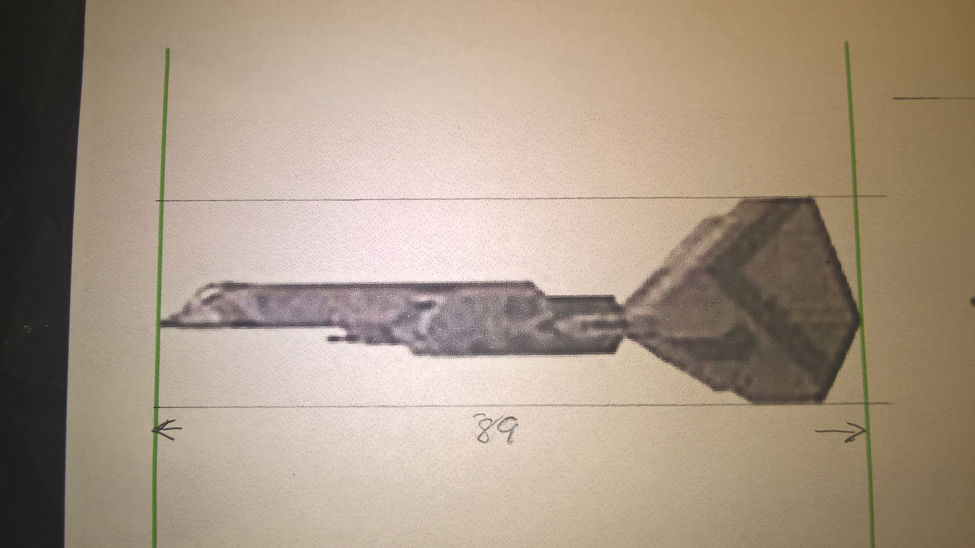
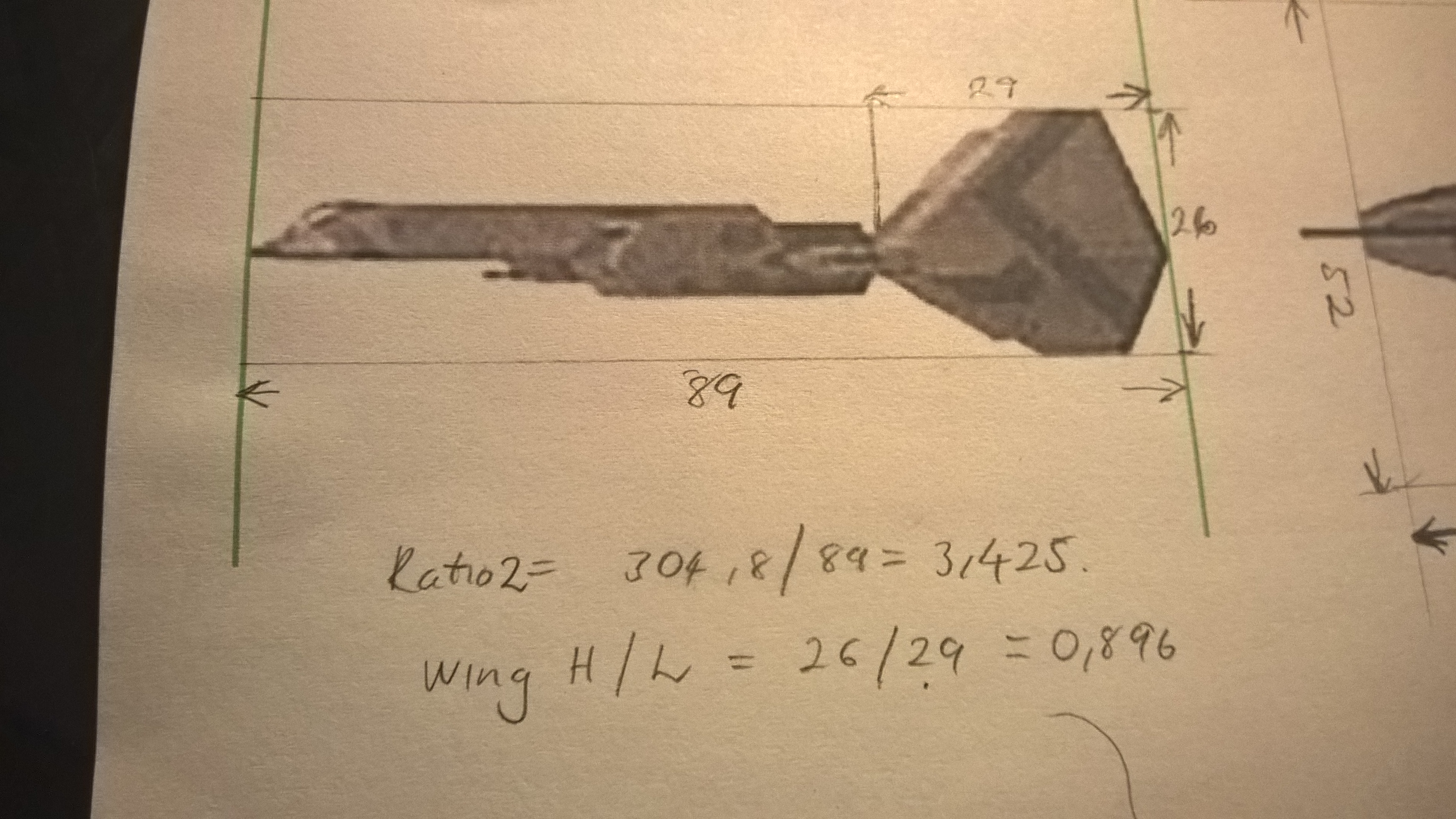
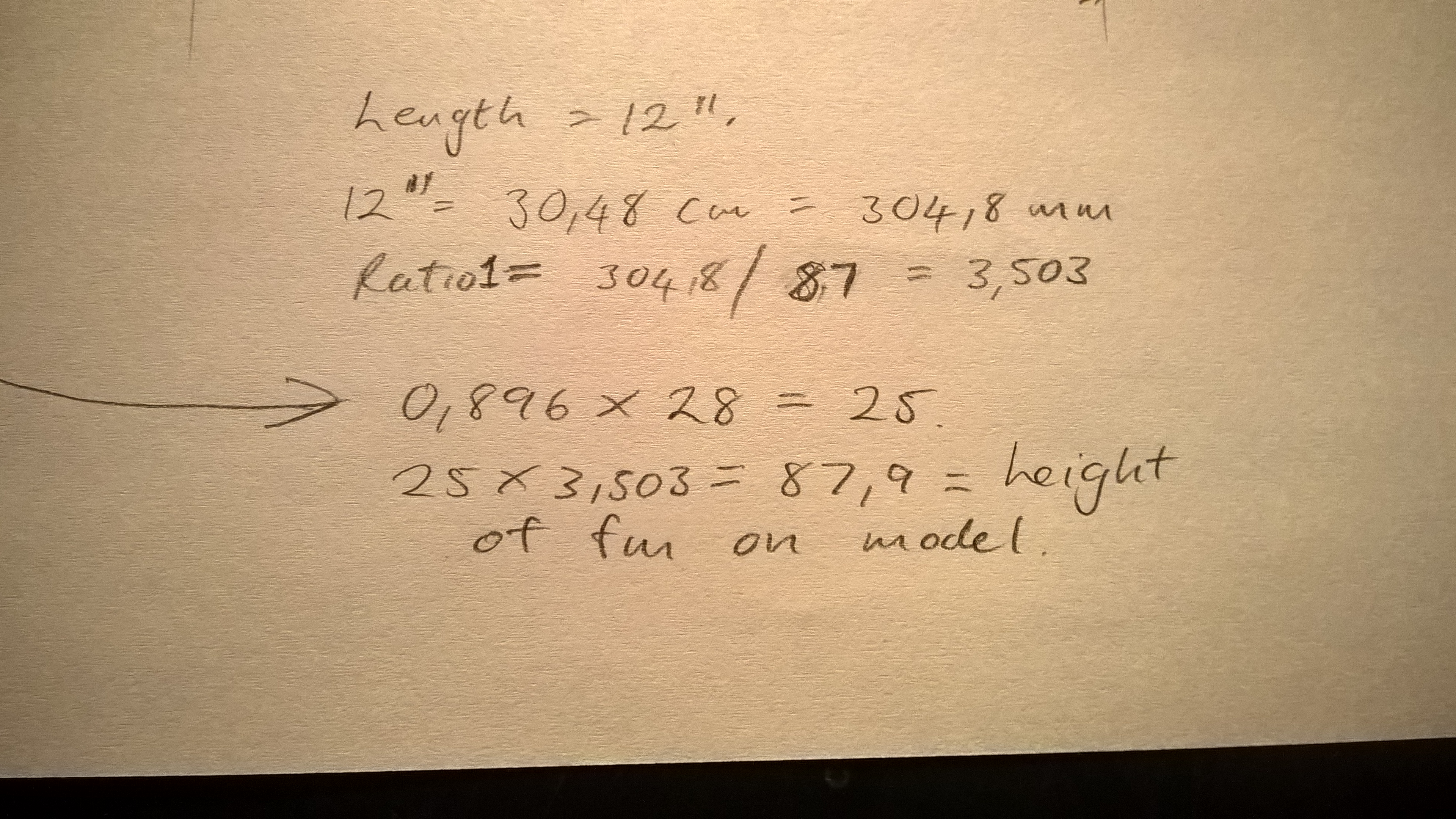
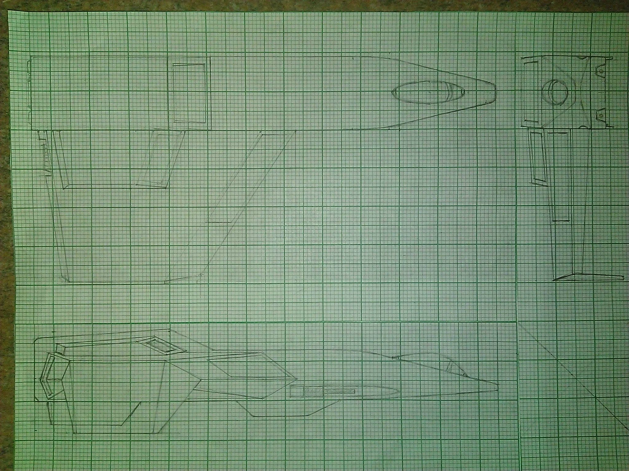
First thing I did was load up Wing Commander: Secret Opts and swap the in-game Excalibur with the Panther Fighter, that way I could control the fighter while I took screen caps of the fighter. So I took head-on shots of the craft from each of the axis angles. I then assembled those images into the collage you see here in Photoshop. I then used the full sized print out to gather measurements of the craft. here is the first batch of measurements.
1YXRAza.jpg


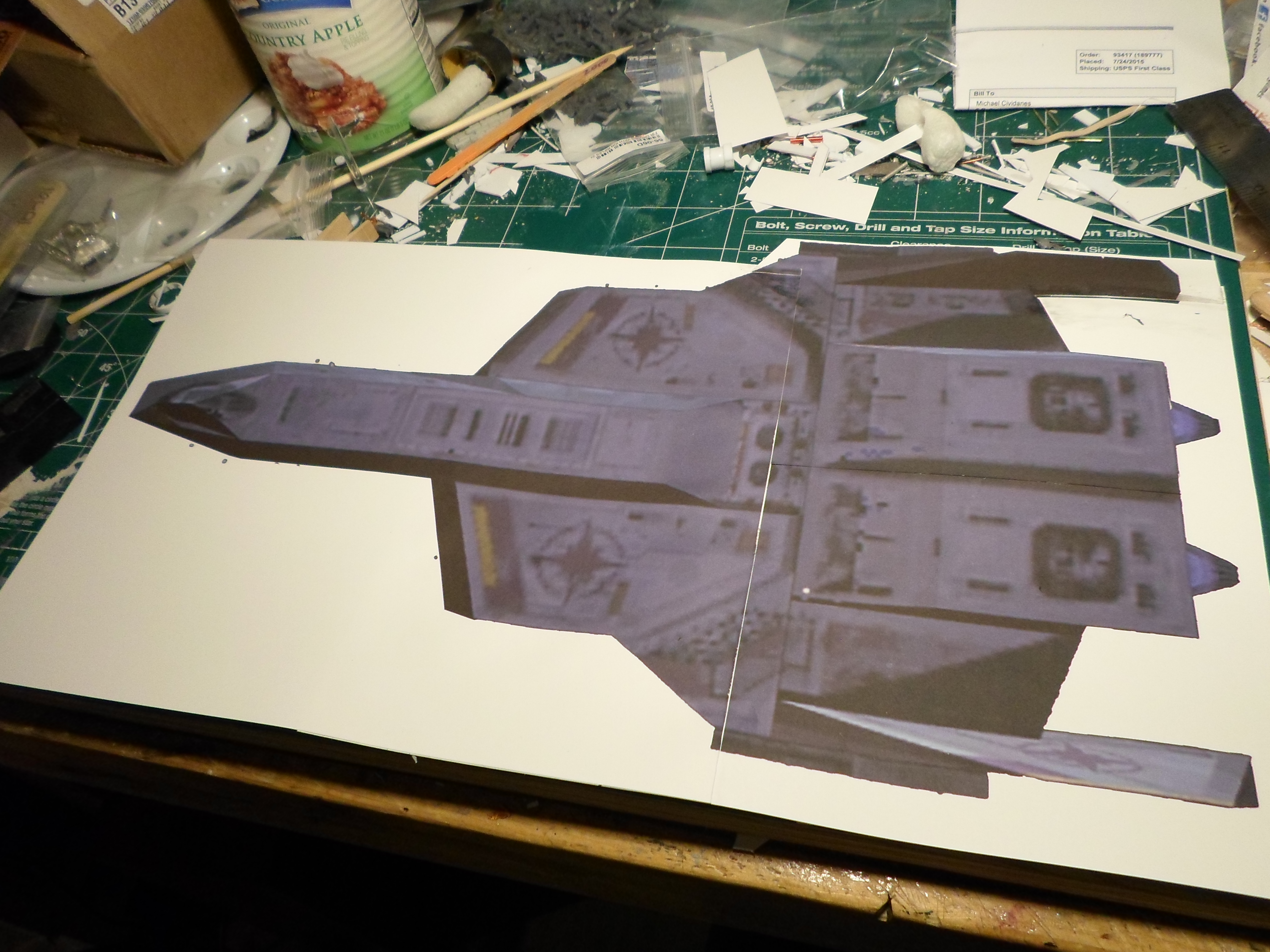
This is the full size print out I assembled of the top-down shot of the Excalibur. Nothing particularly fancy here. Took the top down image, up-scaled it until it was the size I wanted (about 16" in length), and then printed it out. Cut the parts out and glued them together to get one sheet. From this I'm able to take measurements, which I record in the collage in photoshop.
JiiF0iP.png
 
Last edited:
When it comes to WC models some of us are keenly interested in following the manufacturing process (in the hopes it is feasible to do ourselves).

We followed @Whiplash and his balsa wood Hellcat V for a long time and I have to say it was fun to see his progress from blueprint to decal accents. I only wish I had my own. It looked liks a model you would have seen out of an ILM (Industrial Light & Magic) shoot when he was done with it.

Did you use @Péricles design prints to make the Vampire or was it done how you're doing the Excalibur?
 
Last edited:
I did use Pericles' paper-craft designs for the Vampire. The... I don't want to say the word but it's the only one I can think of, the 'problem' with Pericles' plans is they are quit literally the in-game model transferred to paper, which while it makes a game-accurate model, I'm shooting for something that is more universe accurate. The best example of what I mean on the Vampire can be seen in the nose:

If you look at the art work for the Vampire:
WqTV5lK.png


You can see it has a pair of twin-linked cannon barrel barrels (I want to say those would be the particle guns if memory serves based on placement).

But compare that to the nose of the in-game model:
F-109-Vampire-Fighter-V2-Paper-Model.jpg


You can see how the two barrels and assembly have been condensed down into what... well whatever that is. It's just something that didn't get translated from the artwork to the model or vice versa. Also the in-game vampire have a much leaner body thus appearing longer then in the art work.

For the Excalibur I want to go for display value. So I'll be interpreting and adding additional details, but I want to stay closer to the Wing Commander 3 version of the craft, but if I come to a point where I have a source of data from in-game compared to a source of data from say universe, unless I have an explicit reason to do other wise I'm going to take the source from in-universe as more accurate.

As I progress through the project I'm going to be posting a lot of information regarding how I go about things, how I got sizes, how I build parts, ect. I'm going to do this for a variety of reasons, and not all of them personal. As I said, I have no 3D design or architectural experience what so ever, I toyed with Miya for like 20 minutes once about 20 years ago, and have never had enough of an interest to go back into it. I've built.... the dark gods only know how many kit-models and I've converted hundreds more over the last 30 years, so I have a mind for "unfolding" things from their 3D construct to a 2d part. Still, there is a difference between knowing how to unfold an object and knowing how to build it.

So I will be posting pretty detailed progress updates on the project as I go both for a personal record so I can come back to it and see what I did, and to give people with more knowledge then I an opportunity to look at my process and provide feed back. And finally I'll post the detailed info as a basis for anyone else who wants to give it a go. I seek to inspire after all.
 
Last edited:
Oooh yes, this one grabbed my attention right away! Thanks for the call, @Whistler.

@Adm_maverick, welcome to the wonderful world of scratch building! Always good to meet a fellow model enthusiast. The snaps of your workbench above made me smile, I can tell you. :)

I've been cobbling kits together for 20-odd years myself, which is great fun, but there is something extra special about doing everything from scratch. It also provides you with almost limitless scope to learn, experiment, and take risks in a way you can't really do with a plastic kit.

I'm particularly excited to see you tackle the Excalibur; it's a long-standing favourite of just about every Wingnut I've ever spoken to. Also, 16 inches? Wow! Scope for insane amounts of detail right there. I built one back in my late high school / early varsity days that needs a bit more love and attention to really be up to, erm, scratch.

So anyhow, as Whistler mentioned, I recently chronicled a project that will perhaps interest you and maybe provide some inspiration.

https://www.wcnews.com/chatzone/threads/the-hellcat-v-refit-project.26785/

If you'll permit, I'd like to share some of what I learned along the way. For starters, I'm very happy that you are shooting for in-universe accuracy; that's the main reason I substantially rebuilt my original Hellcat model. To that end, I would strongly advise against taking measurements directly from the in-game 3D model. I built my first batch of WC ships that way, but the results were disappointing in many respects. The game models are simply too low-poly to really give accurate dimensions; they were severely limited by the tech of the day. Those screen-grabs can be very useful for getting paint colours or surface details though.

If accuracy is what you are after, I would recommend alternative sources. What you really need to get hold of are shots of the detailed models used to film the FMV sequences. There aren't a wealth of those available, but if you for instance grab the GOG version of WC3, you get the complete library of FMV sequences with the game, and can play them at your leisure looking for good Excalibur shots.

There is a another priceless reference that really busted the case of the Hellcat V wide open for me: The WC3 Warbirds poster. Have a look at the snip I uploaded. The three drawings at the bottom are a tad small, but I think you'll find that using those as a base for your overall dimensions will result in something that is much closer to the in-universe ship.

At any rate, I look forward to the adventure! Good luck and have tons of fun.
 

Attachments

  • Excalibur Warbirds.jpg
    Excalibur Warbirds.jpg
    40.5 KB · Views: 61
Last edited by a moderator:
Anytime Whiplash, I love this stuff.

If you need some real good Excalibur FMV, check out this
youtube upload of Kilrathi Saga. Some real nice close-ups in this one, and even get a Dralthi IV in the shots to help with scale.


There is also some good stills available in game. Any shot where the Excal is spotted on the deck with one of the maintenance crew works great.
 
Indeed, love that video. It should do nicely for some detail shots. I went a bit nuts, and downloaded a tool that can do frame by frame decomposition of a vid into jpg files. You end up with thousands of pics, but it's better than hitting pause or print screen.
 
I can easily extract the individual frames from the video... but then what would I do? While I understand that it possible to determine measurements and the like from the individual frames, I do not know how to accomplish that. So... okay I have an image of the Excalibur with a Dralthi in the back for scale.... um. Okay. How do I determine the width of the engine sections from that image?

Beyond that, I've already reached out to Klavs81 to see if he would be so kind as to toss up some axis aligned images of his Excalibur model that I can use in replacement of what I'm already attempting to do.
 
I can easily extract the individual frames from the video... but then what would I do? While I understand that it possible to determine measurements and the like from the individual frames, I do not know how to accomplish that. So... okay I have an image of the Excalibur with a Dralthi in the back for scale.... um. Okay. How do I determine the width of the engine sections from that image?

Fair point; it's tricky to try and measure anything from a video frame unless the ship is aligned along an axis. That's why I would work from something like the Warbirds poster primarily, and then use the videos for spot checks and to discern fine details.

As for how to determine the dimension of any object from a screengrab, well that's fairly straightforward. You just need to compare a known measurement to the picture and then determine a scale. For example, say you get a nice top-down shot of Excalibur from a video, and print it out. Say the ship is 5.2 inches long in the printout. Your want a 16 inch model, so simply divide 16 by 5.2, and then scale up every other measurement from the printout by that ratio.

This may seem like a lot of effort, but it works. The more good shots you can find, the better your accuracy becomes.
 
Last edited:
Okay so I took Whiplashs suggestion, well the first part of it anyway since this is most certainly not going to be a quick process, and shifted gears from using the in-game models for size and measurements, and instead using alternate imagery, such as the Warbirds file info on the Excalibur. I also grabbed a metric crap ton of frames from the Kilrathi Saga intro and several in game videos from Wing Commander 3 showing the Excalibur. For the moment they are just sitting my library and due to the video shots they will be of little use for getting measurements. But as Whiplash suggested, they should be a good option for detail checks and the like. I've also gone back through my library of pictures (I've been collecting images from the internet ever since I discovered the "Save image as" command when I was about 12 years old) and collected several images I have of various artistic renderings of the Excalibur. Like the Screen Stills, I'm not sure how much measurement value these will have, but again they provide details that aren't as visible in the smaller images or the in-game shots.

Beyond all of that I did start crunching some numbers for the model again based on the Warbird images. I've decided I'm going to scale back a bit for the project and rather then do a 16" long model, I'm going to do a 12" long model instead. I've done lots of small scratch build jobs before, but never a full blow from the ground up total scratch built model before. And I'm thinking about doing some lighting effects in the model as well. So the 12" version will be easier to manager and I think closer to my skill set at present. I want to challenge myself, not waste my energy and materials.

So, I took the warbirds image and pulled it into Photoshop where I upped the size by a factor of 6 so I have some room to work and make notes. The image is small enough that I will be forced to 'interpret' a lot of details, but that's what the reference library is for. With the image in Photoshop I started working out some numbers. I had to go way back to Algebra and Geometry to remember how to work with scales and conversions for this and I'm not totally sure my math is accurate. So if anyone who actually knows what they are feel see a mistake, please point it out.

So, the length of the Excalibur in Universe is stated as being 32 Meters.
The image from nose to back of wing tip comes in at 1.458" in length. So if I want to convert this to a 12" model, I'll need to multiply the measurements by 8.25 to get the right size (I think) With the image being 1.458" long compared to the 12" model (based on a 32 meter long ship... is anyone else getting a head ache?), I'm figuring that every 3m in the image needs to translate to 1" in the finished model.
 
Last edited:
Jip, that's a mighty fine collection of stills you have there. They ought to come in handy.

As for the measurement ratio, you've got the idea. Don't worry so much about the 32m fictional length; that will only come into play if you build additional ships and want to ensure that they scale correctly compared to the Excalibur. For now, just concentrate on the target length of the model, which is a defined and fixed number.

Word of caution on those drawings: The measurements may be a bit skewed in some of them. Objects closer to the camera appear larger, and all that. The top/bottom view (i.e. the middle one) will be your best friend for getting overall proportions right. I would not for instance use the side view to get the overall length, since the vertical fin closest to the "camera" is clearly already a bit bigger than it should be due to perspective scaling. If you measure it from the top view, it should be spot on.

The side angle will however give you a lovely view of the general shape of the fin, so you'll be able to glean at least some information from it.

I'm off to work soon, but I'll do a more complete write-up later on of a few tricks you can use to ensure your measurements are consistent.

It may seem frustrating, but as Mr Monk used to say, you'll thank me later.
 
Last edited:
OK, so I've done a bit of thinking and come up with a few basic tips and examples you can use. These are just suggestions, so if you want to take a different route or try something simpler, that's perfectly fine. I'm very pedantic about details and I enjoy making detailed drawings, so for me, creating a set of plans is half the fun. Anyhow...

1) Find a reliable source for measuring, preferably a plan view (top/bottom, front, side) with as many "true length" angles as possible. Shot that are angled or have significant skew due to depth of field are no good. Tick this box since you have the Warbirds drawing.
2) Print out the picture(s) and make them as large as is practical. Reason being, rulers are only so precise, and a tiny drawing is very hard to measure from. Also, if the size difference between the drawing and your planned model is very great, making a small measuring mistake will get compounded when you multiply it to get the final value.
3) Settle on the total length of your model - Also done, you've picked 12 inches, henceforth to be referred to as 304,8mm.
4) Select a reference that allows you to correlate the planned model length with the reference picture. The top view is ideal since it shows you the true length of the ship with no funny angles. I like to block the drawing in so that I can use the rectangle as a guide for the ruler, and as a reference for marking out certain dimensions. You'll see what I mean in a moment.

yzCq6ao.jpg


5) Now, determine the ratio of the reference to your model. The math is quite simple; The reference pic is 87mm long, so the ratio works out to 304.8/87 = 3.503. Save this value! Write it down, memorize it, whatever, because this is the golden rule you will be working with from now on.

vfMUL6b.jpg


6) Now that you know how long the reference picture is in relation to the model, you'll want to start filling in the blanks. The more known dimensions you have relating to the final model, the easier it becomes to gain useful information from other reference sources. So how about the overall width? Well, it measures at 52mm on the drawing, so that means: 52 x my scale factor = 52 x 3.503 = 182.2mm. Voila! Now I have another value to work with besides just the overall length.

V96Sx0Y.jpg


7) Rinse and repeat the above for as many parts of the ship as you possibly can. You need to be very clear on where every component is and how big it is in relation to everything else. Mark these values out for reference (another reason why having a big printout helps). See some examples below.

XF6QfR5.jpg


8) Once you've learned as much as you can from a particular angle, you can move on to other sources. Say you now want to figure out how tall those wingtip fins are. Well, the top view isn't going to do much good, so you need to use the side view. But oh dear, it's not the same size as the top angle!

DrrLX8g.jpg


You could now compute a second ratio for this angle, but this may get confusing very quickly. There is also the question of whether that fin is in fact to scale with the rest of the ship since it's clearly closer to the camera. Here is what you do:

9) Convert unknown values to knowns by using your first drawing as reference. We marked out above that the fin is 28mm long in the top view. I can also get that measurement from the side view, and it comes out to 29mm. Not a huge difference, but let's be pedantic about this. The height of the fin in the side view is 26mm. That means that the height-to-width ratio of the fin is 26/29 = 0.896.

uDXHbKk.jpg


In which case, the height of the fin in the top view would be (26/29) x 28, or 25mm. Still with me?

Now I can use my original scale ratio to determine the actual height of the fin on the model.
25 x 3.503 = 87.9mm

IOMnAf1.jpg


OK, I hope that wasn't too confusing. You should be able to use a similar approach for other source material, as long as you can relate it back to a known measurement you took earlier.

In the end, what you would want to get out of all this math business is something that looks like this:

S4TEP9A.jpg


You can of course use a 3D modelling package, but I'm old school. :D

Let me know if you have any questions about my ramblings.
 
Last edited:
You can of course use a 3D modelling package, but I'm old school. :D

Let me know if you have any questions about my ramblings.

I suppose I could use a 3D modelling package... if I had one or knew how to use one. Yeah I have basically 0 3D design experience. I understand the basic concepts involved in 'unfolding' a 3D object into a 2D flat, and I can kind of work forward from that concept.

That being said, I really appreciate the break of your design process. It helps shed a lot of light on the approach and the hows of why it worked for you. It also gave me some inspiration for a new direction to take the project. As you said, trying to measure the warbirds image that is less then 2" long is only going to lead me to compounding errors from earlier in the project. Don't ask me why, but that clicked with me in regards to digital graphics. I'll explain:

See in digital graphics you have 2 types of graphical engines each with their benefits and minuses to design. The first is known Raster graphics, or sometimes referred to has bit-map pictures. This format uses individual colors dots to render an image. The more dots you have in a given space the sharper the image can be. A line is simply a series of dots of comparable color. This format has the advantage of being capable of storing far more graphical information and being the foundation most directly based in traditional art work so many of the concepts from that medium translate to this format. The second type of graphic is known as Vector graphics. These use mathematics to form shapes rather then recording each individual position of every point contained in the image. This has the advantage of being vastly easier for a computer to deal with but doesn't translate from math to art very well.

Why am I bringing this up? Well, the two graphic types have another consideration between them, how well they scale up or down. See a bit-map can only be scaled by either adding or removing details. How the program add details will effect how well the image scales up, but generally you can only scale a bit-map image up about 50-60% before you start seeing a noticeable loss in sharpness as additional quasi-random extra material is added.

As an example, look at the corner on the right side of the Excalibur image where the forward section of the fuselage meets the side of the wing and side mounts. On the 1 1/2" sized image it's moderately decent.
WqRAT8Z.png


But enlarge it about 400% (so that the over all image would be about 4.5" long for reference) and suddenly it stops looking anywhere near as sharp.
nIQeJXt.png


Vector Graphics however, because they are mathematically based can scale infinity. The program simply remaps the location and calculates what's between the points as needed.


So why did I just explain all of that? Well you gave me the idea to start with a series of vector graphics, based on the Warbirds images, then upscale those vectors to the size I need them. Since the vectors expand infinitely, there's no lose of detail in the process. I started with just tracing the major sections visible on the Warbirds image. I did some digging and found my hard copy of the Wing Commander 3 stuff and scanned the warbirds images at an obscenely high resolution of 2700 dpi then pulled that scan into photoshop (as an aside, it's always a challenge working with 5"x2" image that's a staggering
400megs :eek: 
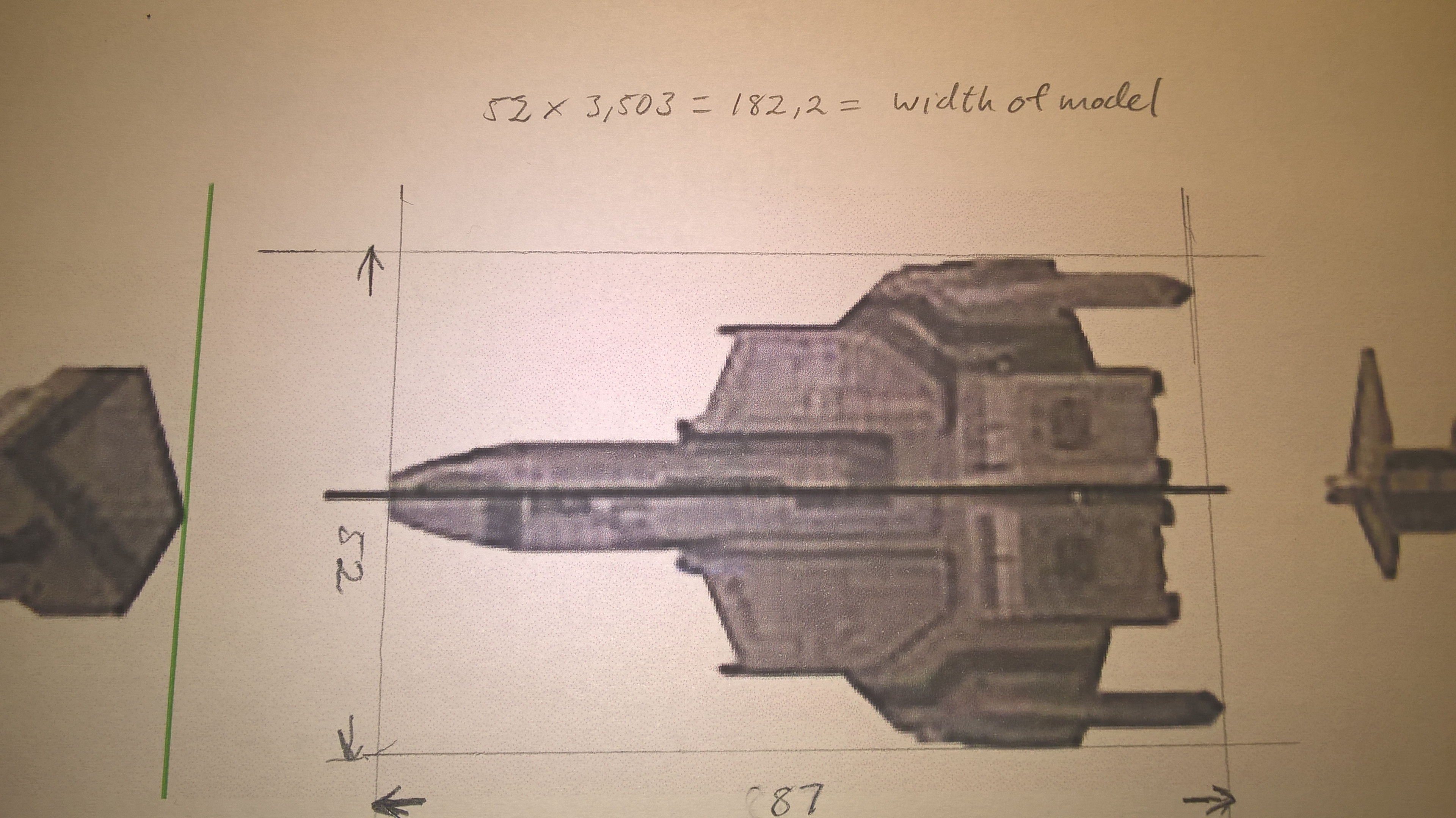
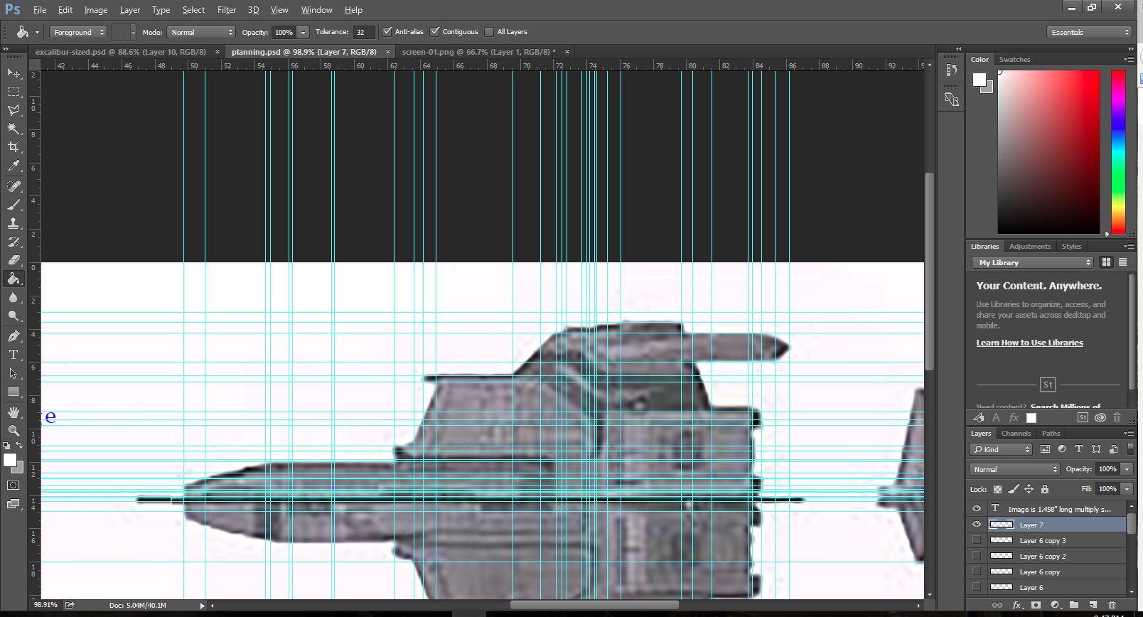
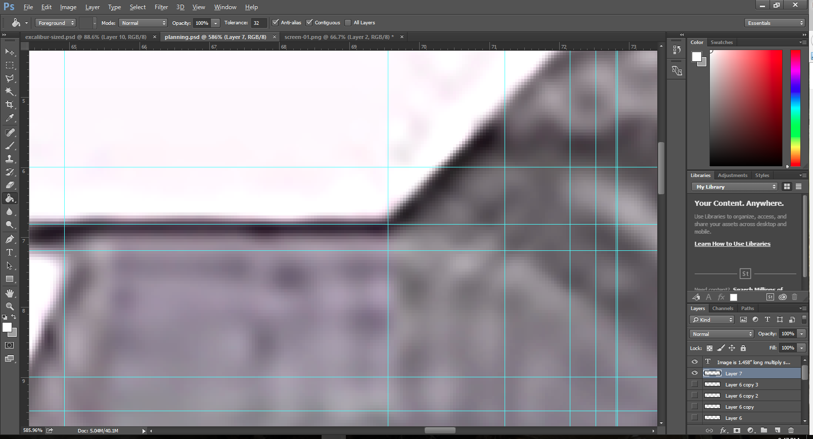
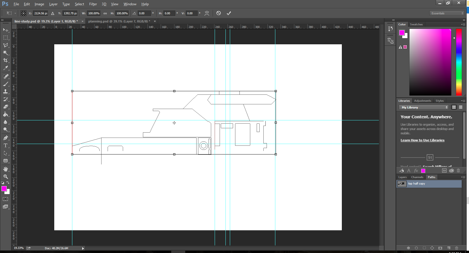
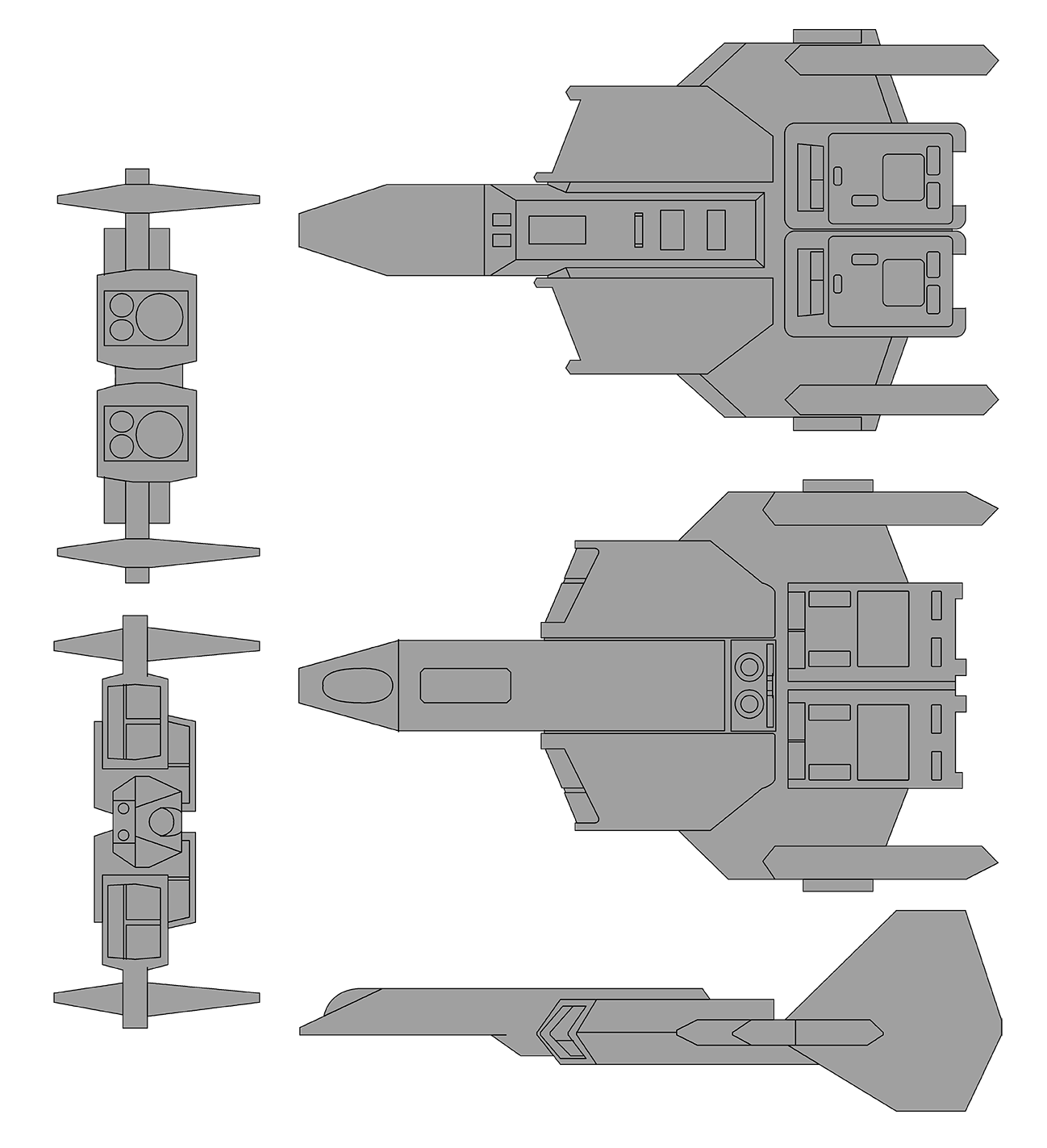
in size) and went to work with the pen toll to generate the vector graphics. the high resolution pulled out some details, but the size of the original image simply doesn't have a lot of detail to start with.
VoKF4Rn.png


Remember how I said enlarging a bit-map image is done by adding material? Well scanning a printed image at such a resolution results in basically the same thing. End result? I could trace out the body, the engines, and the cockpit. The rest... eh I kind of had to take some artistic license with those.

Remember that library of images I assembled of the Excalibur? Well I used that a lot in this process. I primarily referenced the "armada" rendering of the Excalibur for filling in the details that were lost in the up-scaling of the scan.
So after a couple hours worth of work, I assembled the following top-down image of the Excalibur with
yNPv8bG.png


I mentioned that these are first passes, why is that? Well... it's because they don't match up exactly with each other. It's too late for me to go into all details but as an example. The widest part of the front boom where the cockpit is, it is widest on the front view, narrowest on the top view, and just slightly narrower in the bottom view.

So what does this mean? Well, it means I have to go back, pair up the line art pieces with each other and decide which part of which version I want to take as the 'correct' version. While the web version of the image above sizes out to be about 4" wide, I want to build a 12" model from these designs. So if I scale everything up by a factor of 3, and I have one part from the bottom that is 1mm wider, then the same part from the top view, but the rear version is 1mm to the left, I'll wind up with a part that started out as a rectangular cube but when built comes out as a lop-sided rhombus. So guess what I get to do over the next few days....
 
Last edited:
All I can say is, well done! That's part of the fun and the beauty of scratch building: You use any tools at your disposal, and whatever approach you are comfortable with.

I'd say this is a great first pass. The overall proportions look spot on to me. As you mentioned, you need to get the scale consistent between the different angles, and then it's a matter of getting the finer details right.

Off to a good start then. Have fun!
 
So, this may seem like a silly question to ask at this point, but is this going to be a papercraft model?
 
So, this may seem like a silly question to ask at this point, but is this going to be a papercraft model?

the ultimate end result will be mostly a plastic model. Probably use some balsa wood for spacing and battery mounts. Also going to have some lights in it so... yeah.
 
the ultimate end result will be mostly a plastic model. Probably use some balsa wood for spacing and battery mounts. Also going to have some lights in it so... yeah.

Interesting... So that means plastic sheet, I would assume. Never worked with it myself, I went all-balsa when I started scratch building.

Note to @ChrisReid; This isn't a paper model as per your front page post.
 
Last edited:
Oooohhhhh, that workspace... Man, you have a fantastic setup. Most of my models were built on my parents' dining room table :)

Also, I have friend who's a huge 40k fan and has a few miniatures he's busy painting. Will definitely send him the link, he'll enjoy your work tremendously.
 
Back
Top