Searching floor plans for WC1/2 capships

Excellent, Marc - I should have looked in sooner!! Where does that come from?
I didn't want to pester BradMick yet, because he's got a lot of stuff to do on his own, and as this doesn't even classify as a project (although I'm not so sure anymore), I wanted to wait a bit until I REALLY get in trouble...

Well, that contradicts what I have done so far in some points, but those can be modified.

LeHah, the comment about the obvious error confuses me a bit - I was going to put a repair deck under the flight deck too, but where's the mistake? (I guess some part of fiction I can't remember, so help me out here.)

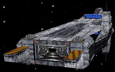
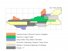
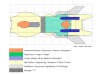
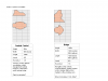
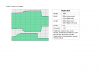
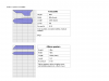
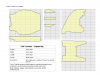
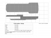
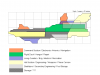
So here's a little schematic I've cobbled out in the meantime in coffee breaks, using the silhouette from the WC2 manual. Since only the side view is ready by now, it may be a bit confusing, but the general idea was to identify "sections" in the model, so that sizes and therefore room locations can be guesstimated.. - opinions and corrections welcome!
 

Attachments

  • WC_C_schematic.png
    WC_C_schematic.png
    4.9 KB · Views: 216
Your scale seems off.... 100m long? thats less than the legnth of three broadswords.
 
criticalmass said:
Excellent, Marc - I should have looked in sooner!! Where does that come from?!

I'ts my own 3Dversion of te Concordia, and there in lies the problem: it's no 100% accurate. Some parts are a bit off in scale or lengh. (that's why I suggested Brad)
 
Now I'd Love to see a Concordia Class Layout. I *am* working on that as we speak.
Also your size is WAY off. I mean get it up to like 1,000m and you'll be damned close
 
bah, its not pestering when its beneficial to someone. ask away, hit me up on AIM or MSN or something, i'm generally always on. if you need it, and i got it....you'll have it 30 seconds after you ask, or something like that :)
 
Just to clear up some confusion - the TCS Concordia (CVS-65) seen in Wing Commander II is a Terran Confederation-class dreadnaught. "Terran Confederation" is the name of the class. A "Concordia-class carrier" refers to the carriers in Wing Commander IV - the TCS Lexington (CV-44) and the TCS Princeton (CV-48).

From the old /ships database:

wc2confederation.jpg


Terran Confederation-class dreadnaught

wc4carrier.jpg


Concordia-class carrier
 
Last edited by a moderator:
AD said:
Your scale seems off.... 100m long? thats less than the legnth of three broadswords.

The scale's definitely off - it should read 1 square = 100m, as the whole ship is 987m long. Sorry for the typo - that way the Mars mission got lost, I know.

BradMick - thanks for the offer, I'll get back to you on that once I get to the actual graphics...

LOAF - as always, thanks for clearing things up. I got confudes by the encyclopedia entry "Confederation class Dreadnought". Darn, it shows that I'm quite the infantry guy, doesn't it?

Powell99 & all the others - don't put your hopes too high, I'm NOT creating fully detailed graphical deckplans, but a "room structure". It'll look something like the attached pic (although this is the development view, ingame it either is a *bit* prettier or not shown at all. Dang, did I say ingame?). Anyway, I'd be interested in you basic layout of the ship, powell99 - feel free to comment.
 

Attachments

  • TESTmap.png
    TESTmap.png
    24.7 KB · Views: 187
criticalmass said:
It'll look something like the attached pic (although this is the development view, ingame it either is a *bit* prettier or not shown at all. Dang, did I say ingame?).

So it would run somewhat like a more elaborate version of what we see in wc3, yes? Makes sense to me.

I always found that the few places there were to go in wc3 made the victory feel alot smaller than it probably was (as is evidenced in the elevator transition video)
 
Update - and hopefully some peace and quiet for this thread:

I've taken the pictures kindly supplied by you guys, identified a couple of sections in the top- and side view, balanced both views against each other and extracted some measurements. The results are attached.

And now, one last time - feel free to comment, rant, spit tobacco juice, or sing...
 

Attachments

  • Slide4.PNG
    Slide4.PNG
    5 KB · Views: 159
  • Slide5.PNG
    Slide5.PNG
    6.3 KB · Views: 160
Uh-oh, I didn't know that you can only upload two attachments, so you have to suffer some doubleposts...
 

Attachments

  • Slide6.PNG
    Slide6.PNG
    4.2 KB · Views: 150
  • Slide7.PNG
    Slide7.PNG
    2.9 KB · Views: 148
...at least the attachements are small - less than 10KB.
 

Attachments

  • Slide8.PNG
    Slide8.PNG
    3.2 KB · Views: 126
  • Slide9.PNG
    Slide9.PNG
    5 KB · Views: 136
Last one.

Sorry for this mess, but I don't have access to webspace right now - I promise I'll get some as soon as I get off work.
 

Attachments

  • Slide10.PNG
    Slide10.PNG
    2.8 KB · Views: 141
Looking good but I have my doubs about the length of the flight deck. For the Dreadnaught to have a full complement of fightercraft (which can be considered just as full as a fleet carrier) you'd think that the flight deck extends almost the entire length of the ship but between the Phase cannon and the outdoors.
 
Fellentos said:
Looking good but I have my doubs about the length of the flight deck. For the Dreadnaught to have a full complement of fightercraft (which can be considered just as full as a fleet carrier) you'd think that the flight deck extends almost the entire length of the ship but between the Phase cannon and the outdoors.


On the WC2 concordia most of the runway is outside the ship. So it's likely that alot of the maintenance and fighter storage is on the decks below... how far they strech forward into the ship, I dont know.
 
In my mind the section you define as the 'forecastle' was the command and control/targeting area for the phase transit cannon. In fact, in my mind, the phase transit cannon and all its components essentially run the entire length of the underside of the ship.
 
There's only one, minor issue that I see, beyond what's been mentioned by others: The orange section up front is unlikely to have the CIC, as traditionally (a tradition that seems to be upheld with the Intrepid in WC4) the CIC is located as near as possible to the center of the ship, to try to put as much protection around it as possible. If the CIC were in that exposed part, it wouldn't do much more good than the bridge, as far as vulnerability issues are concerned.
 
Wow, thanks for the feedback, gentlemen!

As I said, everything I did up until now is based on guesswork, so I'm really glad to get your input. There are some points where I wholeheartedly agree, and some parts where I see your point, but I'm hard pressed at finding alternatives.

Flight deck: This is speculation - the ship has its acceleration/deceleration runways on the outside, so the fighters don't move much in the actual pressurized deck, I guess. In my plan, the deck is 300x210m, that's about 12 football fields (or almost the length of the USS Nimitz) on the "indoors" flight level. Counting 2-3 storage/repair levels above and below, that might be enough for 120 fighters... but... - please advise.

Forecastle: I'm not at all sure about that structure myself. In some pictures it looks like a giant belly fin and might be a forward stabilizer or maneuvering device, in some others it seems to have rows of windows. I defined that thing as crew quarters because housing the crew inside the hull, between antimatter reactors, the PTC and other dangerous stuff seemed less appealing to me, apart from the tendencies in shipbuilding to design the hull as a housing for the technology, and to tag on living quarters where they fit best, after everthing else has been implemented. (And, a gondola-type thing is more romantic -lots of portholes and windows.) As for its vulnerability - yea, I see that, although placing it on the top where a landing craft can crash into it would be even more vulnerable. The belly position, surrounded by turrets and shield emitters, made sense to me.
BTW, question: I didn't find the crew size of that ship - I estimate at around 1000-1500 (no, I don't have the WC1/2 playguide. #&%$# mail order bookstores). I wonder if the fo'c'sle and the officer quarters are enough to house all those people...
EDIT: I just found a reference on the Fleet Tactics site stating that the ship has a crew of 3000, which is okay. Estimating the size the living quarters and dividing that up by a generous 30sqm per crew member, there's still enough place for everybody, functional rooms included.

Front tower: That structure between the runways really puzzled me. Exposed, in a dangerous place (easy to be hit by a starting/landing vessel), rather large, it needs to be something important. But what is it? Death, I see your point about tradition, but all the other ships I looked at didn't have a second bridge/tower structure. I dubbed it as CIC on a purely hypothetical basis - the ship's a dreadnought, with an offensive weapon and a fighter complement. So there are two roles, which may be managed independently - and which are both so important that having two separate structures for security, backing each other up if one is hit, made sense to me (although the source of that thought is the architecture of a tank - divide driver and cannon operator. As I said, I'm an infantry guy.) Suggestions, anyone?

Well, anyway thanks for all the input - it's a fun ride, and I'll see where it takes me.
 
Several things:

Maybe my last line yesterday sounded a bit too final - I was dragging myself away from the screen and back to work, so maybe you got the wrong impression. I have the feeling that this is far from over yet, so stay tuned.

Update: I've already created basic structures for some areas (independent from their actual position - that comes later when areas need to be connected), and it is FUN! I've jotted down some notes about a possible plot - need to watch that, and my schedule, but a mini-project is on its way.

I was kindly made aware of a major design gap in my definition exercise: The Phase Transit Cannon isn't inside the main hull structure, but more or less attached below. So I have to redo some bits and pieces. Bang there goes the forecastle.

Confirming that, and also questioning some other definitions I made, Marc has sent me a beautiful cross-section of how he envision's the ship's enterior layout. (I wish I had a 3D modelling tool for my company laptop, but in my line of work that would be had to argue.)

As today's News topic is the Conconcordia and the PTC anyway, I don't want to keep this piece of art hidden - I hope Marc doesn't object to this. I had to cut it a bit (took out the non-transparent mirror images) to get it in an uploadable size.

Here are his color code definitions and the picture:
blue means living area and everything related.
green means hangar and hangar related areas.
orange means all related components of the phase-cannon.
red is everything related to engines or maneuvering thrusters.
violet is storage.
white is all that is radar and sensor (mostly automated).
yellow is command and control.

Comments welcome!
 

Attachments

  • marc-xsection.jpg
    marc-xsection.jpg
    61.2 KB · Views: 163
It would seem to me that you haven't designated enough space for storage, as long as this definition includes fuel. As well, it may make more sense for the powerplant to be more central, closer to what youve made the PTC tower (on the bottom) Speaking of which, on a second look I see engines but no actual power plant?
 
Back
Top